Creating PCB Assemblies from your Altium PCB Project
If you use the EDA Tool Altium to design your PCB Assemblies, the best method to upload your design files to MacroFab is to create the following manufacturing package to upload to the MacroFab platform.
- After modifying a binary version 3.0, or 4.0, or 5.0 PCB document, run command File » Save to open this dialog. Options/Controls PCB Binary Version 6.0 - Click on this option to save the current PCB document in PCB Binary version 6.0 format supported by Altium Designer 6.3.
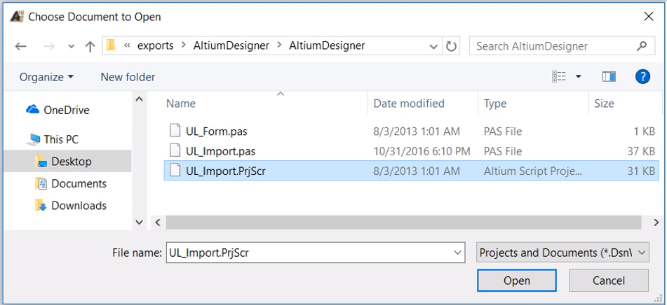
- In Altium Designer, open a new.PcbDoc file: (File New PCB) Once the new.PcbDoc file is open, proceed to File Import Altium PCB When prompted, navigate to the appropriate directory and selected the.SWPcbDoc file.
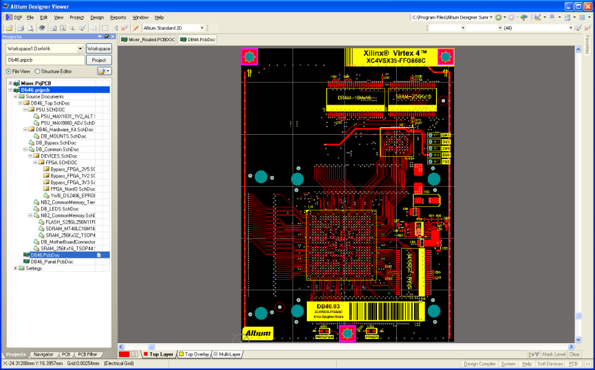
- Altium Designer’s Free PCB Viewer Download Allows You to Explore Your BRD Files Today, it almost seems if there are as many PCB design file formats as there are PCB manufacturers. Using a custom file format is advantageous when working with the originating company’s program.
- ODB++ Manufacturing Packet
- Bill of Materials from a .XLSX spreadsheet
The model data is stored (embedded) in the PCB file. Link to Model – Select a Model file from a folder registered in the Choose Model dialog – typically, the file might be shared with an MCAD designer. This file will be linked to the 3D Body, so any file updates made in the MCAD domain will be detected by Altium Designer when the file is. The way I've been trying to do the import of Gerber files into an Altium Designer PCB document is that I open a new PCB document and then I import one Gerber file at a time by choosing File-Import-Gerber File. I stop after the first import since I just get a mess of tracks and pads. Added to original post (2) Just opening the Gerber file.
Once you have created these items you will be able to easily upload your PCB Assembly to the MacroFab platform.

In the PCB tab, simply drag-and-drop your Altium manufacturing package into the file upload target. Alternatively, you can click the Upload Files button on the right side of the screen. More information about uploading files to the platform can be found on the knowledge base article Creating a PCB and Uploading Design Files. The Bill of Materials .XLSX format upload procedure can be found here.
Altium ODB++ File Generation
ODB++ files are exported directly from your PCB and include the PCB layers and placement data needed to build your design. Open your design in Altium and navigate to the PCB view.
To open the ODB++ export window click File -> Fabrication Outputs -> ODB++ Files.

Selecting ODB++ from the fabrication output menu will bring up the following window showing the output options.
Make sure all of the boxes in the Layers to Plot section of this window are checked and press OK. Altium will now automatically generate all of the necessary manufacturing files. This may take a few moments. Once the file generation is complete Altium will generate a new folder called odb in the directory where the PCB file is saved.
Bill of Materials Generation
For the Bill of Materials Auto Fill to work on the MacroFab Platform, Manufacture Part Numbers (MPNs) must be supplied for the components. MacroFab currently does not support MPNs in the ODB++ file so a .XLSX spreadsheet will have to be made to associate MPNs with component designators. The spreadsheet only needs to contain designators and the corresponding MPN. For more information on making a .XLSX formated spreadsheet and uploading it see the knowledge base article, Importing a Bill of Materials Spreadsheet.
Generating this Bill of Materials .XLSX file is optional for Altium PCBs. You will be able to fill out the Bill of Materials without MPNs. The platform will use the footprint and value provided by the ODB++ file to suggest parts. See the Bill of Materials Management article for more information.

Additional Altium Questions?
If you have any other questions about creating a PCB Assembly with a Altium PCB Project please contact our support team.
Tags:
Recent Articles
Top KB Categories
Category Articles
Design Rule Setup
Downloadable Files
Our Kind customer has provided loadable DRC rule and Stackup files for our multilayer services.
How to load RUL files
JLCPCB Milti_Layer Rules.rul
How to load Stackup files
JLCPCB-4-Layer-Stackup.zipJLCPCB-6-Layer-Stackup.zip

Note, these files are not exhaustively validated or guaranteed by JLCPCB. Use your judgment and always verify your designs meet our capabilities to prevent design defects that could affect your boards. If you have corrections or find errors, please email support.
Generating Gerber file
1. Open your .PCB design files on Altium designer software
Select File -> Fabrication Outputs -> Gerber Files.
2. General Setting
In the General Setting set the precision to 2:5 (0.01 mill resolution)
3. Layers Setting
Please make sure you have the clear outline in mechanical layer.
If your board are 2-layer, there will be no inner layer(G1,G2,G3....)
Include the layers that you want to export by marking these, lect “Used On” in Plot Layers, Select “All Off” in Mirror Layers.
4. Aperture Setting
Be sure to mark “Embedded apertures (RS274X)”

5. Advanced Setting
When you make sure all configurations are fine. Please click the OK to generate the gerber files.
Gerber Files are automatically loaded in the Altium cam viewer. This tool allows you to verify that all layers have been generated correctly and that they are all in positive mode.
Generating NC Drill File
1. Generate the Drilling layer in Excellon format.
File -> Fabrication Outputs -> NC Drill Files
Altium Pcb Viewer
2. Set the precision to 2:4. Then click OK.
Then you get all files. Please put them into a single zip/rar file.
Altium has published a guide on producing those files here:
http://wiki.altium.com/display/ADOH/NC+Drill+Output+Options
Open Pcb File In Altium Excel
If everything looks OK, upload the zip file to JLCPCB order page.


